Description
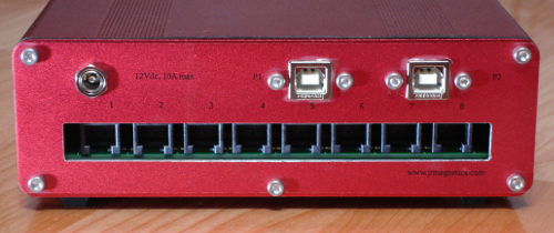
The hub supports eight independent RS485 networks with two control lines and power. Status indicators on the front panel correspond to the state of the CMOS input line on each port. Command line instructions configure the hub on USB port 1. Communication with any one of the eight selected RS485 networks is accomplished by command line instructions on USB port 2. Any legacy security device can be connected which includes passive BMS, passive infrared motion sensors and other devices that send status over USB port 1. Power at 12V on each port is current limited to 2 Amp by polyswitch current limiters that automatically resets when the short or over load is removed. The sum total of the current drawn by all ports must not exceed 10 Amps.
The USB ports are accessed on the PC like COM ports by applications such as Hyperterm, Putty or Hercules on Windows systems or Putty, CuteCom or a standard terminal interface on Linux systems using command line instructions. There should be two windows open on the PC at once; one (P1) for issuing commands and monitoring the status of each input port line and the other (P2) for communications on the RS485 port selected by instructions given on the command line through the other window (P1). If no RS485 devices are attached, then the USB P2 window is not necessary.
General
The JRNET100 features a legacy interface to existing security devices such as magnetic contacts. Each input sensor line has a 10KOhm resistor connected for either any contact switch to ground or open collector transistor operations. The normal state is low. The input line change of state from low to high (the corresponding LED on the front panel switches from green to red) is identified by port number and observed in window 1 connected to USB P1.
The CMOS output line on each port sends a 1 msec pulse by command line instructions sent through the window connected to USB P1. This pulse will be sent down the output line corresponding to the actively selected port. This function can be used for actions such as "remote test" or "device reset". All units with their input lines connected in parallel on that port will receive the pulse. |
Mounting
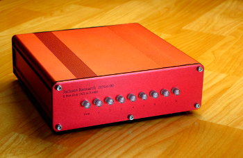
The anodized all aluminum NEMA Class 4 housing standard mounting is desktop. Brackets are available for wall mounting which should always be oriented with the back panel, RJ12 connectors, pointing down to avoid accumulation of contaminants and moisture within the enclosure. Except for the RJ12 connectors on the back panel, the unit is sealed.
Network Device Configurations
One possible configuration is one legacy magnetic contact per port. More than one magnetic contact may be in parallel on the same port, but the message on that USB P1 will only indicate a fault on that port and not indentify which contact opened. Any connected device other than a contact switch, such as a motion sensor, must have open collector output for proper operation all of which may be connected in parallel.
One RS485 serial network string may be connected to each port or any combination of RS485 networks and sensors.
Care should be exercised not to exceed the individual port output current on any line. If more power is needed, it should be supplied near the attached device by an external source.
Network Port Cables
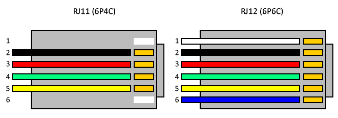
There are eight (8) RJ12 modular P6C6 connectors suitable for standard six conductor telephone cables and jacks.
Operation
See the manual for full operation instructions, command line instructions and wiring configurations. |