 |
|
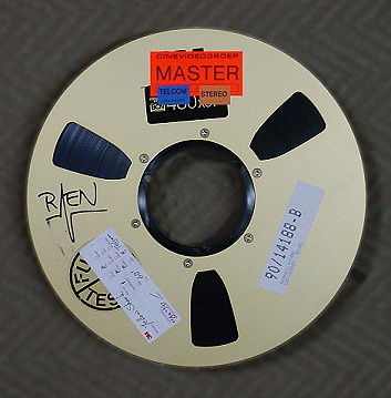
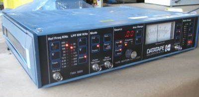
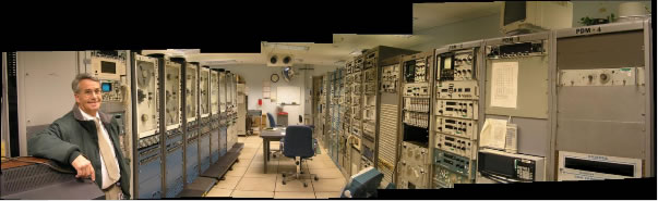
| The Data Evaluation Lab (DEL) at the Goddard
Space Flight Center is the only known place that has the equipment
and expertise to playback the 1" wide magnetic tapes and to recover
data. |
|
|
| |
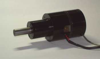
Jackson Research has the original
blue prints (literally) for these capstan motors for the MARS tape
recorder (M-22). The MARS recorder was much smaller than the 3700B,
but used the same magnetic technologies. The motor in the photo
is from a limited production facility in the basement operated
by John Jackson and two others. The shaft is ground from sintered
Tungsten. The optical recorder used a light image pipe to double
the line count for a 10k lines per revolution tachometer built
into the rear of the assembly.
Silver was sputtered onto precision cut optical grade glass
disks. The high line counts were photo etched from very large
photo masks which were optically reduced to minimize mask errors. |
|
|
| |
| The tape recorder capstan motors were
high performance Alnico magnet torque motors in precision machined
housings with integrated optical encoders. The bearings were typically
grade 9. These motors were controlled in closed PLL loops
designed by Eugene Cooper and Henry Martiya. |
|
|
| |
IRIG 28 track assemblies had seperate
record and read interlaced head assemblies resulting in four
heads per assembly. The cores were hot pressed ferrite with sendust
tips. The highest record frequency was around 1.5 MHz with
20dB S/N ratio. These high definition 28 track one inch head
assemblies were used in airports to rrecord all flight date in
the control towers. Also, the marines were using it in intelligence
gathering. Several of the manufacturing phases had been improved
with the last one fine grinding after alignment of the gap depth
in a specially built tool fixture using 15 microinch glass gap
head assemblies in a linear - as opposed to the Ampex quad heads
- video recorder. Also, initial layout of solid state head assemblies
and sputtering of sendust on quartz substrates were made. No
problem with alignment here and 100 channels per inch were easily
achievable. The economy got into a slow down and B&H closed
the lab.
|
|
|
| |
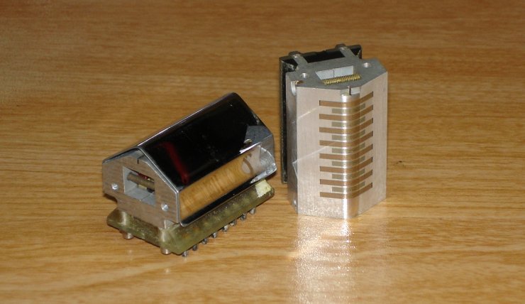 |
| These read/write heads were given to Jackson Research
by Al Bakowski, Bell&Howell's magnetic head specialist. |
| |
|