| |
|
 |
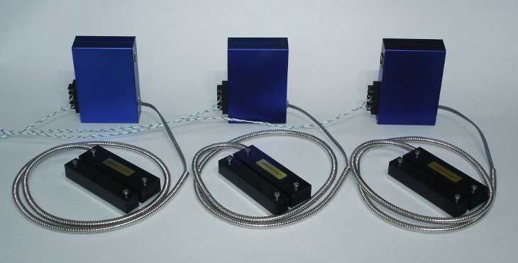
| Figure 1: Three switches of the BMS Magnetometer type connected to a conventionally wired system. |
|
 |
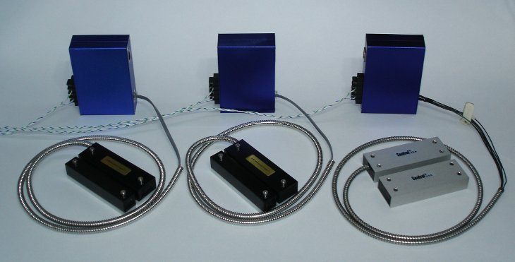
| Figure 2: Three switches, two of the BMS Magnetometer type and one from an existing system, connected to a conventionally wired system. Remote test terminals are available on the barrier strip. |
|
 |
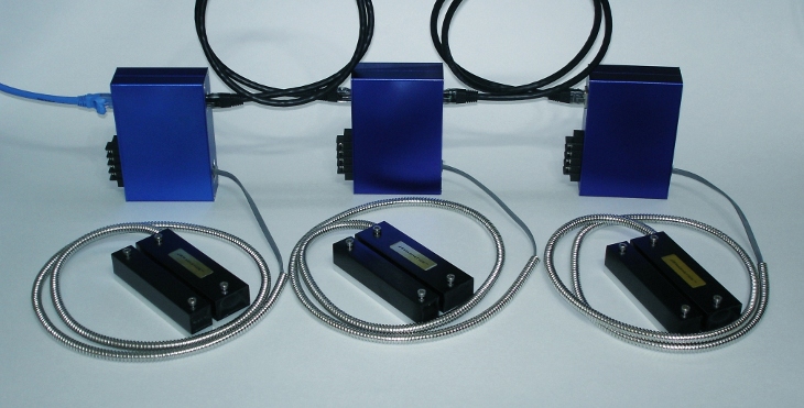
| Figure 3: Three switches of the BMS Magnetometer network type connected as nodes on an RS485 network. |
|
 |
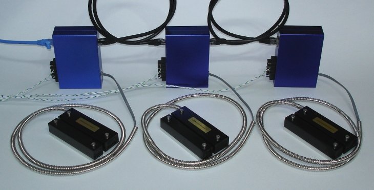
| Figure 4: Three switches of the BMS Magnetometer network type connected as nodes on an RS485 network and to a conventionally wired system in parallel. This configuration uses an existing installation without modification and allows a network to be built up on top of it with a string of ethernet cables. Remote test can be initiated from either system without collisions and register correctly on both systems simultaneously. Any existing system can be upgraded one node at a time. |
|


